FREQUENTLY ASKED AIR TURBINE QUESTIONS
Can I leave the AIR wires disconnected to my batteries?
Always make sure to push the negative and positive together (short circuiting the turbine) if you’re going to leave the AIR X disconnected to the batteries for any length of time.
Can I use an external charge controller to regulate my AIR?
If you want to use an external charge controller, we recommend only diversion load-type charge controllers with the AIR.
How do I connect solar panels to my AIR?
Solar and the AIR can work together, but you cannot connect the solar panels in line between the turbine and battery. When installing, ensure that the wind turbine and the solar go into separate battery terminals.
How do I find my serial number?
The AIR serial number can be found in three places:
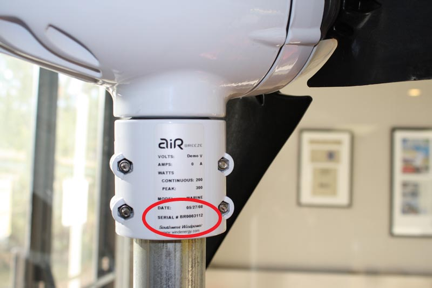
- On the product manual, there is a sticker with your turbine's unique serial number.
- On a label that can be found on the turbine on the base where it connects to the mounting system
- Inside the base (yaw shaft) under the padding
How do I know the AIR is charging?
The best way to know if the AIR is charging is to install an amp meter in your system. You can also check the LED on the bottom of the turbine, which should be solid on when the turbine is charging. Also refer to the FAQ "AIR Amp Meter Qualifications".
How does the AIR regulate my batteries? Can the output of my AIR be changed by the potentiometer?
The AIR senses the battery voltage and stops charging the batteries at a pre-determined set point. When the battery voltage is achieved, the turbine will begin turning slowly and the LED will blink slowly. The set point is pre-set by the factory, but can be changed by the user by adjusting the potentiometer. This does not change the output of the turbine, only the point at which it stops charging the batteries.
How does wire sizing or voltage drop affect the regulation of my AIR?
Small wire size can allow the turbine to sense higher voltage and shut down early. Use the wire size listed for your system to avoid this problem.
I can measure a small amount of current back-feeding to my AIR. Is this normal?
Yes. Tthe internal circuitry draws a maximum of 20 mA when not charging.
I just installed my AIR with an automotive style amp meter, but I don't see any current. Why?
It's very common to wire the amp meter backward. Try reversing the leads on the meter.
Is lightning protection necessary?
It is always a good idea. The DELTA LIGHTNING ARRESTOR (model LA 302-DC – 3 WIRE – 500 V) is widely used. In addition, we recommend the MidNight Solar – MDSPD – 300 - DC. Grounding your system is also very important in protecting against lightening.
My AIR spins and stops repeatedly. What can I do?
1. Check all wiring between turbine and batteries to ensure that all wires are connected properly.
2. Make sure the stop switch is both wired correctly and in the correct position.
3. Remove the turbine from the tower and bench test according to the manual (refer to manual).
What effect does radio interference have on my AIR?
The AIR normally does not affect radio transmitters, but you should attempt to route power lines from the AIR away from the power and antenna lines of a radio transmitter. One trick is to twist positive and negative wires together, which will cancel out electrical noise created. This can be used on the AIR’s power lines, on the radio’s power lines and on transmission wires. Proper grounding also must be observed. Also refer to the FAQ "AIR Amp Meter Qualifications".
What is the difference between copper and aluminum wire?
Aluminum wire is less conductive, so it must be larger than copper for the same load. We recommend copper, but if aluminum is used, please size appropriately.
What is the maximum wind speed the AIR will survive, and do I need to take it down in a storm?
The maximum wind speed is rated at 110 mph. If you expect higher winds, you can shut the turbine down and tie off the blades or remove the hub and blades. However, you should NEVER approach the turbine in strong wind conditions.
What kind of batteries should I use with my AIR?
Only use deep-cycle type batteries. Car batteries or marine batteries are not intended for this application. Automotive batteries are intended to discharge a large amount of current in a short time. True deep-cycle batteries are intended for immoderate loading, and deeper discharge.
Where can I locate tubing to make a tower?
The AIR X uses 1.5-inch Schedule 40 pipe (outside diameter is 1.875 inches). Try your local fencing or plumbing supply store.
Where can I purchase a stop switch?
The 50-amp or greater single-poled double-throw stop switch can be purchased from automotive repair shops or your dealer.
Why is there a cutout in the tail?
The cut out helps balance the turbine to track the wind and give the turbine stability. In a marine environment this gives it better stability in rough seas, and keeps the turbine pointed into the wind when the boat is heeled over.
Will it hurt my AIR to short-circuit the output?
No it will not hurt the AIR. It is designed to be short circuited as a normal breaking procedure.
Will it short my batteries when I use a stop switch?
It is important to use a single-pole, double-throw stop switch rated for proper current and voltage. This allows the turbine to disconnect from the batteries before being short circuited. This is commonly referred to as “break before make switch.”
Can the AIR turbine be used in a Positive Ground configuration?
The AIR Wind Turbine was successfully tested in a battery positive earth ground configuration with solar (Hybrid System) as shown in the diagram below.
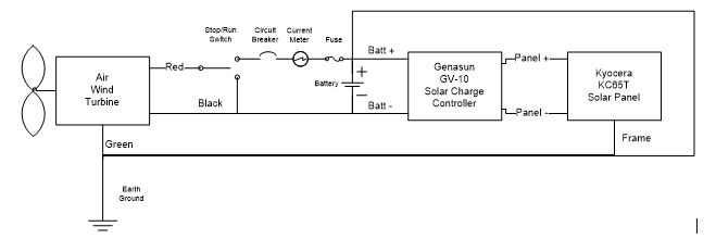
It is important to note that the green wire from the AIR turbine is not connected to the red wire from the AIR turbine directly. There should be only one common earth ground for the system. Please contact Primus Tech support for further questions.
Please refer to the TriStar Positive Ground Technical Note below for more info on positive ground recommendations for Solar and Morningstar controllers:
Where do I find instructions and information on replacing the AIR circuit board?
PDF: AIR Circuit Kit Replacement Instructions – All current AIR Models
Primus Circuit replacement video: http://primuswindpower.com/maintenance-service/warranty1-2/
Can I use Lithium Ion Batteries with the AIR turbine
How do I secure my AIR wind generator for storage and severe weather.
Click here to learn more.
How should I store and secure my AIR turbine when not in use on tower?
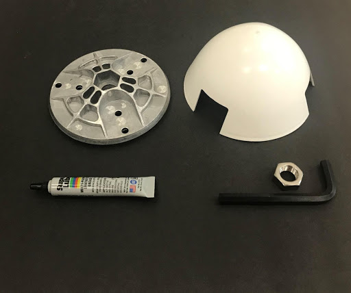
AIR Storage Kit, P/N 2-ARAL-ST-100, Retail Price $39
Parts included (in caption below):
-
AIR 30 Hub – 3-CMBP-1005-01
-
AIR X Marine Nose cone – 3-CMBP-1007-02<
-
Super Lube Multi-Purpose Synthetic Grease with Syncolon (clear) - 3-CAOT-1017
-
Rotor Jam Nut (to secure hub) – 3-HDNT-912
-
5/16 short arm hex key-3- CAOT-1007 (for rotor jam nut)
CAUTION - When the AIR turbine is stored outdoors for an extended period, it is critical the nose cone and hub remain in place, as this prevents water infiltration through the shaft/bearing gap and into the turbine body (nacelle).
DANGER - If turbine is stored when the Blade/Hub/Nose Cone Assembly is removed, there is a high probability that water infiltration will occur and the nacelle interior will rust causing damage. This will not be covered under the Primus Wind Power warranty. To avoid this potential issue, Primus Wind Power offers the AIR Storage Kit.
INSTRUCTIONS -When storing your turbine, remove the Blade/Hub/Nose Cone Assembly and store in safe location to not damage blade set. When The Shaft and Face is exposed, apply a liberal amount of synthetic grease to the gap around Shaft and Bearing on the Face of the turbine (this should be performed as a regular maintenance event every 12 months). Next, attach Hub and Jam Nut and tighten using 5/16” hex key (hand tighten). Attach the Nose Cone with position of the Nose Cone Blade opening not lined up with Blade bolt holes to avoid water intrusion through holes in the Hub.
If you have any questions, please feel free to call Primus Technical Support at 303.235.8944 ext. 3 or email us at [email protected].
Can I send my AIR turbine into the Primus Wind Power factory to be repaired?
Learn More about our Loyalty Program Terms & Conditions here.
Troubleshooting
AIR Amp Meter Qualifications
It appears that the turbine is putting out power, but the amp meter used is currently unable to measure the turbine's output. To more accurately measure the AIR turbine's output, we recommend a clamp-on DC amp meter. An example of one is the Extech DC400 available at Home Depot and other places. Most meters are for measuring AC, so be sure the meter you pick is capable of measuring DC (DC is battery systems, AC is grid power). A clamp-on amp meter is useful for several purposes, such as checking PV or wind system output, measuring device loads, and identifying system problems. It should be part of the tool kit for any dealer, installer, boat or RV owner. For a use like checking the output of the wind turbine, it's invaluable.
A multimeter will not work well for measuring output from the AIR turbine. Most multimeters are only capable of measuring milliamps, and the output of the turbine will typically blow the fuse in the multimeter. The turbine's voltage will be a bit higher than whatever the battery voltage is , but this difference is a variable of the cable size, connectors and length. Using a voltmeter to check the turbine's current output will be difficult and likely won't be a valid measurement, but is useful for general trouble shooting.
The issue with the Xantrex Battery Monitor's is a bit more complex (and possibly other systems that use low voltage measurements and/or noise susceptible communication systems). These and similar monitoring systems use a negative shunt and are not tolerant of AC ripple and noise produced during charging. This means they won't accurately register the AIR turbine's charge. The AIR produces some high frequency noise at 20 KHz, with the amount being variable depending on the RPM of the turbine. It also has some residual lower frequency voltage ripple after rectification of the wild AC from the alternator (rectification is converting the wild AC to DC). The amount will be somewhat dependent on the cable size, length and battery size and charge level (bigger and less charged batteries more readily absorb ripple and noise). This can cause problems for the Link system and possibly some sensitive RF systems such as radios. These issues can be resolved by the use of an in line filter such as the TDK/Lambda RDEN048050 line filter. It is available from Digi-key (www.digikey.com) and other vendors. This filter is suitable for 12, 24 and 48 VDC systems and will handle up to 50 Amps. It is a chassis mount version with threaded post inputs and outputs. It includes both positive and negative battery connections and is bi-directional, so it doesn't matter which side is hooked to the AIR and which is hooked to the battery. It is important that the cases is grounded. This can be accomplished by mounting on a grounded surface, or running a 14 to 18 AWG wire from one of the mounting locations to the system/earth ground. Other DC filters are available from other manufacturers such as Tyco Electronics (Corcom) and Schaffner. Just be sure to use a DC filter rated appropriately for the voltage and current.
Air Makes Clicking Sound
Sorry about the noise you've been hearing. Please check the following:
- The nose cone is not fully pressed onto the face. If it is pressed all the way, and you still believe it is the source of the sound, placing silicone on the nose cone rims that snap onto the blade hub usually does the trick (be sure to place even amounts on all sides).
- Yaw is properly tightened and the yaw is not knocking against the pipe.
- Blades are visibly damaged and a replacement is needed.
- The hub was not placed evenly onto the face and will need adjustment.
- Blades are not properly tightened to the hub and thus misaligned, causing an imbalance in shape or weight.
- The rotor band has become dislodged and is hitting against the stator. Opening the turbine and visually inspecting the rotor will confirm or eliminate this possibility.
- The rotor shaft is bent and the rotor is now contacting the stator. Again visual inspection will determine if this is the case.
Some other possibilities, not as likely in your situation, but thought I would mention just in case:
- Wires down the pipe are knocking around on the inside.
- The Air Yaw Pad inside the yaw clamp is missing and the wires are knocking against the yaw.
AIR Temperature Ranges and Bearing Information
The AIR 40 operating temperature is 14º F (-10º C) to 104º F (40º C), start up wind speed is 7 mph, is quieter than the AIR 30, and can produce energy at a wider wind speed range (will spin in up to 50 mph winds before entering over speed protection).
The AIR 30 operating temperature is 14º F (-10º C) to 104º F (40º C), start up wind speed is 8 mph, is more durable in harsher wind conditions, and produces energy at a shorter wind speed range (will spun in up to 32 mph winds before entering over speed protection).
The grease in the bearings will begin to freeze at temperatures under -10º C but if the turbine begins to spin up, the heat generated will re-liquefy the grease and then it will spin fine. The turbine will generally start up in higher winds to overcome the cold grease but once the machine is warmed up, it will perform normally. Rime ice will collect on the machine and prevent it from operating but once the sun melts the ice or its manually removed, AIR will function normally.
AIR Vibration Issue
If you are experiencing vibration or wobbling of your AIR unit I recommend checking:
• Hub not placed evenly on the face and will need adjustment
• Blades are not properly tightening to the hub, causing an imbalance.
• The yaw clamp is no longer tight to the pole and will need re-tightening.
• The two face bearings are bad and need changing. They no longer spin smoothly and freely when you spin the rotor shaft by hand.
• There is too much “give” between the body casting and yaw. When the body casting is grabbed by hand and lifted vertically upwards, there is play between the casting and yaw. This may need a yaw bearing replacement or the inner bore of the body casting (where the yaw is located) is ovalized and will need replacement.
Bearing Replacement Instructions
Face Bearings:
First you will have to remove the hub/blade assembly, which is secured by the rotor jam nut. It can be done with a 5/16" hex key wrench. Remove the face assembly, secured by 3 bolts, using a 5/32" hex key wrench. Pry off the face using a small flat-head screwdriver. Be careful not to damage the paint on marine units. You may discard the old o-ring and later replace it with a new one.
Ideally you would wear an anti-static wrist strap while doing the next step, but at least be careful to not discharge static electricity to the circuit board. Now use a 7/64" Allen key to remove the three small screws connecting the stator wires to the circuit. Try to feel the factory torque setting (10 in-lbs) on these bolts when you remove them, so as to avoid stripping the threads when you reattach the stator wires. Carefully note the routing of the wires connecting the stator windings to the circuit board. Note the parallel orientation of the three stator ring-terminals and how they are isolated from one another.
Firmly press the rotor shaft with your thumb to separate it from the stator. Moderate force will be necessary to overcome the magnetic field that holds the rotor inside the stator. Use a flat-head screwdriver to pry the stator from the body. This is done by inserting the blade of the screwdriver into one of the three recessed areas where the stator meets the body of the unit, and carefully prying the stator out a little bit. Work your way around the stator prying little by little at all three of the recessed points until the stator is removed.
Now you are down to just the face plate and bearings. There is a snap-ring holding the bearings in place. Use snap-ring pliers to remove and insert the snap ring. Note that the sealed bearing faces out and the shielded bearing is closer to the inside of the body.
To remove the old bearings, align a pipe, dowel rod, or socket with the outer race of the bearing, and use a hammer to tap out the old bearings. Note that the two wavy washers go between the bearings so that the slots in the washers are pointed in opposite directions.
In some cases you can simply push the new bearings into the face by hand. In other cases, you will have to carefully use the hammer and socket/pipe/dowel/etc. to gently tap on the outer race of the bearings and tap them in. After you have the non-shielded bearing in, put the two wavy washers in so the slots do not align, and the two spacers. Then install the shielded bearing so the shield faces out. We use a jig and press in the factory, as the other attachment ("air face wop.PDF") shows, but for practicality in the field this is the next best method. The rest goes back together in the opposite order.
Yaw Bearing:
For the yaw bearing, we apply a tiny streak of lubricant to the yaw bore in the casting before pressing in the bearing. This link (click here) shows the product that we use. The bearing is then aligned and pressed into the body. Then the snap rings are inserted so that they make full contact with the inside machined groove.
Blades
There are a few ways blades will fail: UV damage (non-black blades), cracked at the root (warranty issue), and cracked away from the root (due to a strike – not covered by warranty).
If the blades broke at the root, i.e. where they attach to the hub, then the replacement and related damage is covered under warranty.
For blades that break away from the root, we do not cover it under warranty, as the only way to explain this is that the blades were struck by a foreign object. The wind does not do this sort of damage.
Spins Slowly
An AIR turbine spinning slowly or not spinning indicates a short, which could be present in the system or in the turbine. In order to find out where the short is, the turbine should be “bench tested.” Please see page 26 of the owner's manual for a description of the bench tests.
These tests require you to take the turbine off of your tower, and use only the red and black leads from the turbine. That way it's isolated from the rest of the system, and if the test results are normal, then you know that the problem lies outside of the turbine, in a connection or wire issue.
Spins up, shuts down
By following this guide, you will find the source of the "spin up, shut down" behavior of your AIR. First, I would like to explain that the AIR turbine needs a small (milliamps) amount of electricity to operate its internal circuitry. The circuit board requires at least 10.5 volts for a 12V turbine, or it will be running open circuit. When in open circuit mode, the turbine will spin until it charges the circuit board, then the LED will illuminate and the turbine will brake suddenly as a protective measure. Once stopped, the circuit card discharges and is unable to maintain braking (since it's not connected to the battery voltage it needs to operate) and the turbine will spin up again.
This can be caused by a number of factors. Please begin by checking the following:
• Check the battery bank voltage. It must be at least 10.5 volts (assuming a 12V system) for the circuit to work properly.
• Check all wire connections for a failed or weak connection.
• Check the inline fuse or circuit breaker for an open condition.
• Make sure the wires are properly sized for the length of run, as described in the manual. Undersized wire will cause the turbine to enter regulation mode whenever it produces high current.
• If you have a stop/brake switch, remember that if the toggle is in the center position, the turbine will be in open circuit mode. Try running the red and black wires from the turbine directly to your battery bank, bypassing all inline components. If this fixes the problem, the issue may be with one of your inline components or in the wiring.
• Make sure you are not attempting to run the turbine through a solar charge controller or any diode containing device.
If your wire and connections are good, then the next step is to test the turbine.
These tests require you to take the turbine off your tower, and use only the red and black leads from the turbine. That way the turbine is isolated from the rest of the system, and if the test results are normal, then you know that the problem lies outside of the turbine, and is actually a connection or wire issue.
Lastly, while the turbine is down, it is a good idea to inspect the inside, particularly the brush-to-slip ring connection. The brushes are located on/near the circuit board, and can be accessed by removing the face and the yaw assemblies. Please follow the instructions in the circuit replacement kit to remove the face assembly and access the circuit board and the yaw assembly which has the slip rings. The instructions have references to the owner's manual.
Once you have taken off the face assembly, remove the snap ring on the yaw assembly, as shown in the attachment. This will give you access to the slip rings. Use Emory cloth or fine grit sandpaper to clear away carbon debris buildup and smooth out grooves. Next, put the slip rings back in so they are contacting the brushes. Being careful to discharge any static electricity and avoid touching the circuit board, place sandpaper or cloth on the slip ring. Rotate it so that it rubs against the brushes, and move it back and forth to clean the brushes.
While you have the turbine opened, check around the circuit board to make sure the components are fully intact. Make sure no components are burned or have become detached from the board. And again, be careful you don't discharge any static electricity to the circuit board. A little shock will damage the board. Also check the condition of the brushes the make sure the brush wires are not frayed.
Call 303.242.5820 | [email protected]